
NB: I have added three pics at the end of this post. (28/11/2015)
You may remember that I recently asked you a simple question: ‘Why is there any “soldering” at the bottom of the “1” shaped pad of PT/35(b)?’
(See : PT/35(b): A Very Simple Question – UPDATE )
Several readers have suggested an explanation but quite frankly none works. (I think we all agree on that.)
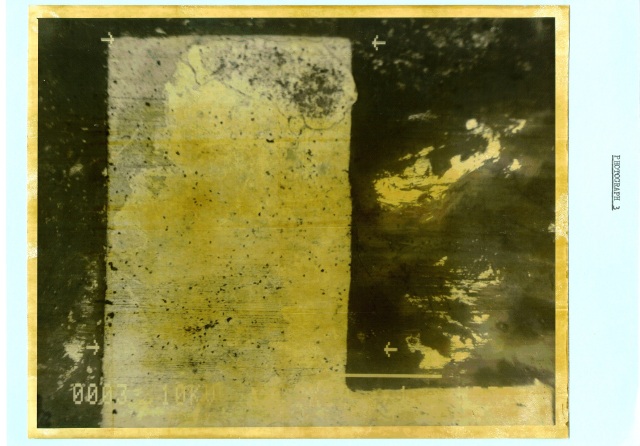
Again, look at the “Lead/Tin soldering” deposited at the bottom of the two following pictures.

–

And now look at how the relay is mounted on the main board of the MST-13 Timer! No soldering at the bottom of the pad is needed. (This pic comes from a control sample made after the identification of MEBO.)

Please, REMEMBER that there is no evidence that this “soldering” was present on the early pictures of PT/35(b)…
UPDATE (28/11/2015)
Here are two pics of K1 (the TOGO timer found in 1986)

–

There is clearly no reason for the presence of any soldering at the bottom of the 1 shaped pad as nothing is to be attached there…
–

–
And yet the presence of soldering is very obvious. (Although it does not extend all the way to the right side of the pad.)
I can only think of one explanation. And it is not an “innocent” one. But, as always, I will let you come to your own conclusions for now.

Several readers have suggested an explanation but quite frankly none works. (I think we all agree on that.)
I don’t agree, not yet. The explanation still appears plausible to me.
This discussion is proceeding under a false assumption, as far as I can see. These “control” items were all supplied by MEBO and came from the Thüring workshop. They demonstrate the soldering that would have been carried out to populate the boards as MEBO (Lumpert?) would have done it.
The only thing we really know about PT/35b is that it wasn’t one of the Thüring boards. It’s a clever and apparently deliberate copy/fake. We don’t know who made it or for what purpose. And we don’t know what that person decided to solder on to the board, or why. Just because MEBO wouldn’t have put solder there, doesn’t mean the mystery counterfeit merchant didn’t solder something there.
That being the case, there’s no reason to dismiss the rather obvious and plausible hypothesis that the solder in that position was there all along but was squashed into a different shape when the board was clamped to cut it.
LikeLike
Disagree with the comments.
This photograph dispels the suggestion of any overlap after or during cutting happened;
Also note, any solder mask present is intended, amongst other things, to prevent such an occurrence.
The cuts to the fragment were performed at Siemens laboratory, Germany using the most high tech least destructive equipment available with slow speed machine, diamond cut saw.
To suggest direct pressure or a direct grip or clamp was used to perform the cut is nonsensical.
As an example, due to the cut overrun the fragment was freely pushed through a slow speed band saw.
One cannot place direct pressure on an object but also freely run through the saw, also, where would the direct clamp go ?
The one issue I would draw attention to is why the horizontal cut and the perceived right angle cuts are not similar, at least horizontally similar to the already machine cut at the top of the ‘1’ of the fragment.
I would have thought the machine cut at the top of the ‘1’ would be a great guide to follow for the first cut of the two.
The slightly weird thing is originally the ‘1’ is off centre from the top of the board but the horizontal cut is closer to the same angle as the original top of the board.
LikeLike